Creative Speculation
Related: About this forumBalsamo Busted, again
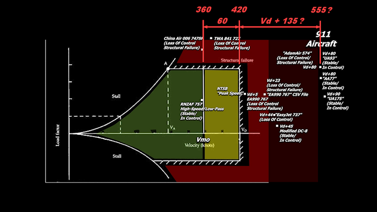
Rob Balsamo continues to insist there is no margin of safety beyond Vd/Md (Design Dive Velocity), and as "proof" he has presented several versions of Vg (velocity/g-load) diagrams with a red wall at Vne (Never Exceed Velocity). My contention is that the conditions in FAR 25.305 are limit cases, not ultimate, and therefore a factor of safety is required for ALL stresses at those speeds. Balsamo has not been satisfied that the FAA and engineers on two professional forums agree with that; he persists in asserting that planes are designed according to his own misconceptions and faulty definitions.
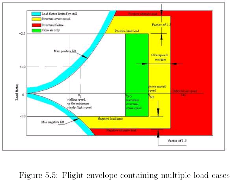
However, here is a similar diagram, but from a structural engineering perspective, i.e. when a 1.5 factor of safety (yellow) is included for ALL loads that planes must withstand, not just the g-loads shown on a Vg diagram:

http://aerostudents.com/files/aircraftStressAnalysisAndStructuralDesign/reader.pdf
There in yellow, past the Vne, is the margin of safety that Balsamo asserts doesn't exist.
wildbilln864
(13,382 posts)you hang out here round the clock huh. Must be nice to have so much free time.
You ready for that next spanking from jdX? ![]()
William Seger
(12,166 posts)johndoeX
(268 posts)Seger, do you see the lines with the arrows at the "Factor of 1.5"? Up and down?
They are describing the 1.5 Factor of Safety vertically, the upper and lower limits (positive and negative G loads). The horizontal Overspeed margin is not 1.5. In fact, it is only 10% between Vne and Vd as manadated by the FAA.
You would know this if you read anything you have posted.
I posted the Vne diagram to keep it simple for people like you.. and the fact it is in Flying Magazine read by thousands of subscribers... from passengers, to students, to professional pilots.
Jets do not have a Vne and havent since the 60's.
I guess we now know why Seger is no longer a "draftsman".... he can't even understand a simple Vg and the 1.5 factor of safety designated by the upper and lower arrows in the diagram he posted...
![]()
wildbilln864
(13,382 posts)johndoeX
(268 posts)Seger shot himself in the foot by posting the above VG.
In fact, the out-of-focus text in the Structural Failure zone (red zone) at the left and right arrows designating the "Overspeed Margin" is Vd.
The VG diagram he posted above is based on light aircraft, but basically has many of the same definitions as Jet aircraft, except Vno and Vne were removed from Jets in the 60's. Jets accelerate so fast that pilots were exceeding Vno on a regular basis. They were replaced with Vmo... but Vd is still the end of the flight envelope and the start of the structural failure zone for both types of aircraft.
VG diagrams expressing "Structural Failure" at Vne are used for inexperienced pilots as there is only a 10% margin between Vne and Vd. So basically, only 10-20 knots.
Do you think Seger will admit he is wrong?
![]()
wildbilln864
(13,382 posts)not a chance!
johndoeX
(268 posts)Not only did Seger screw up pretty bad.... but he also threw Beachy under the bus....
I suppose Beachy will be along sometime soon making multiple posts saying, "The VG Diagram posted by Seger is FAKE!"
![]()
At least mine are a bit nicer to look at...

![]()
William Seger
(12,166 posts)Don't you know that wildbill cares about the truth?

William Seger
(12,166 posts)I found a clearer version of the graphic:

The blurred text just says "Indicated air speed, IAS" (and I'll be looking forward to your admission that you were wrong ![]() ). Your assertion that the yellow zone is just the difference between Vne and Vd is just that, an unfounded assertion.
). Your assertion that the yellow zone is just the difference between Vne and Vd is just that, an unfounded assertion.
I claim that the yellow zone is the margin of safety that results from applying a 1.5 factor of safety to ALL the loads, not just the g-loads, just as FAR 25 requires. That claim is based on what FAR 25 says about limit and ultimate loads and the confirmation from the FAA that 25.305 specifies limit conditions. As always, your counter-claim is based on nothing but your own assertions and repeated misinterpretation of FAR requirements. You persist in ignoring that FAR 25 at the time required planes to be flutter-free up to 1.2 Vd, which wouldn't make any sense -- and would be impossible to meet! -- if Vd was the ultimate case.
And you have yet to substantiate a single claim that you have made about "impossible speeds," most especially including any relevant technical specification or any actual test results. You don't have the nerve to post your claims about 25.305 being ultimate cases anywhere that an engineer can comment, nor to ask the FAA yourself.
On point after point, you have demonstrated that you don't understand this stuff well enough to even discuss it intelligently. Instead, you persist in simply pretending to know the maximum speed of a 767 and make ridiculous claims about plane substitutions for no apparent purpose. Instead of proving your claims, you insist that they are valid unless someone can prove them wrong. I have done that. The technical game is long since over, but I'll keep up this posting game as long as you like.
![]()
johndoeX
(268 posts)But it is the Vd line.
From the Illustrated Guide To Aerodynamics.

From the FAR's

Seger, have you yet figured out why it doesn't say "Factor of 1.5" between the arrows designating "Overspeed Margin", yet says, "Factor of 1.5" between the upper and lower arrows designating positive and negative G loads?
William Seger
(12,166 posts)... when you can just keep asserting you were right. ![]()
If the two Vg diagrams you posted prove anything, they prove that the point labeled Vne in this diagram (which is apparently for a small plane) should really be labeled Vd for 757s and 767s, because that's the end of the defined flight envelope for those planes! You can't refute that; you are simply ignoring what FAR 25 actually says, as well as the FAA representative and engineers on two professional forums, and instead substituting your own faulty definitions and misconceptions, presented in pesudo-technical babble.
Please note the title of the diagram: "Flight envelope containing multiple load cases." You could read the section it's in to understand what that means (well, perhaps you couldn't, but nonetheless): It's talking about the multiple forces on a plane. Specifically, it talks about how even the wings aren't just designed for vertical loads as you falsely claim, because they are also subject to drag and horizontal moments which must be taken into account by combining ALL the stresses. By FAR 25, each of those loads must be multiplied by a 1.5 factor of safety. Your only response is that you think the 1.5 FoS is for vertical g-loads only. That section (as well as common sense) proves you're wrong.
> Seger, have you yet figured out why it doesn't say "Factor of 1.5" between the arrows designating "Overspeed Margin", yet says, "Factor of 1.5" between the upper and lower arrows designating positive and negative G loads?
Ha! Since I've (unsuccessfully) attempted to explain it to you at least a dozen times now, yes, I've "figured it out." The vertical scale is g-loads, and since they are loads, they can and must be multiplied by 1.5. The horizontal scale, however, is speed, and you can't just multiply the speed by some factor: You have to calculate the stresses and multiple those by 1.5, as required by FAR 25, just as I've been saying all along. The reason that the red edge of this particular diagram is not labeled with Vd or anything else, nor any specific distance given from Vne, is because it's the ultimate strength failure point, and you don't know what that is without actually testing it. Did you find those test results yet? Your claim that Vd is the ultimate strength point has been thoroughly busted, to anyone who has been paying attention, yet here you are just reasserting it as if that should be good enough.
Again, that's the whole point: You make "impossible speed" claims that you can't substantiate because the actual maximum speed is unknown until some unfortunate souls find out the hard way. Instead of substantiation, you demonstrate that you are basing your claims on bone-headed misconceptions and faulty, made-up definitions, both of which are easily refuted.
And again, out here in the real world we know that the limits were NOT exceeded on 9/11. You're supposed to be proving that they were, so there must have been some kind of bizarre, unexplained deception, but all you've got to back it up is obvious misunderstandings and misconceptions, delivered with self-aggrandizing bloviation.
![]() Please proceed.
Please proceed.
johndoeX
(268 posts)Seger says - "If the two Vg diagrams you posted prove anything, they prove that the point labeled Vne in this diagram (which is apparently for a small plane) should really be labeled Vd for 757s and 767s, because that's the end of the defined flight envelope for those planes! "
Vne is 90% of Vd.
Vd is the end of the flight envelope for ALL aircraft. Period.
Jets do not have a Vne and haven't since the 60's. Vno and Vne were replaced with Vmo on Jets.
Do us all a favor and ask your source at the FAA. I have asked you more than 5 times to contact your source at the FAA with your claims. You refuse because you know you will not like the answer and instead spin your wheels here.
Better yet, why not just post your VG diagram from the OP over at pprune with your claim "a 1.5 factor of safety (yellow) is included for ALL loads that planes must withstand, not just the g-loads shown on a Vg diagram:"
They will tell you the same thing I have been telling you.
William Seger
(12,166 posts)... because you didn't have the nerve. You just don't understand their answers, and even if you did, you wouldn't admit it. If you think you can find an authoritative source for your nonsensical claims or for refuting mine, you do us all a favor and get on it instead of 100 posts here just repeating the same nonsense over and over.
As I said many, many posts ago, your entire argument is nothing but personal incredulity from someone who is completely clueless how planes are designed. Why do you pretend to know the maximum speed of a 767 when you don't understand limit and ultimate loads? That's a rhetorical question, because (almost) everyone knows it's to sell nonsense videos to gullible "truthers."
superbeachnut
(381 posts)Last edited Fri Jun 27, 2014, 08:34 PM - Edit history (1)
"Seger shot himself in the foot by posting the above VG.
In fact, the out-of-focus text in the Structural Failure zone (red zone) at the left and right arrows designating the "Overspeed Margin" is Vd.
The VG diagram he posted above is based on light aircraft, but basically has many of the same definitions as Jet aircraft, except Vno and Vne were removed from Jets in the 60's. Jets accelerate so fast that pilots were exceeding Vno on a regular basis. They were replaced with Vmo... but Vd is still the end of the flight envelope and the start of the structural failure zone for both types of aircraft.
VG diagrams expressing "Structural Failure" at Vne are used for inexperienced pilots as there is only a 10% margin between Vne and Vd. So basically, only 10-20 knots.
Do you think Seger will admit he is wrong?" - johndoeX
Where do you find sources for so much BS? List them.
This is funny. Do you make this up as you go, or google some internet journalist to quote mine.
"In fact", was special.
Then the funny part, "based on light aircraft", just like your fake Vg diagram for a 767. Irony, or what.
Remember those days you searched for a real Vg diagram? What was that, 5 or 7 years ago?
Each airplane has its own Vg diagram in its Aircraft Flight Manual. I'll keep looking around for the 757. - johndoeXNever finding a Vg diagram for a 767/757, you made one up.
http://forums.randi.org/showthread.php?t=188863
That was funny too.
johndoeX
(268 posts)Seger claims, "when a 1.5 factor of safety (yellow) is included for ALL loads that planes must withstand, not just the g-loads shown on a Vg diagram"
Do you agree with him?
And if the Factor of 1.5 is "not just the g-loads", why is it not written between the arrows designating the "Overspeed Margin", yet is clearly defined for the G-loads?
This is very simple Seger. This can all be solved with one email.
Email your FAA source and ask him if there is a "1.5 factor of safety beyond Vd based on FAR 25.303". Or why not email him the VG diagram you posted in your OP and ask if the arrows between the "Overspeed Margin" represent a factor of 1.5.
You don't want to ask him this question, because you already know the answer is a resounding.... no.
superbeachnut
(381 posts)As seen on 911, Flight 175 got to 590 mph, and did not fall apart. RADAR and Video verify it was a stock 767. I agree, you Gish Gallop along, posting BS.
"Seger shot himself in the foot by posting the above VG.
In fact, the out-of-focus text in the Structural Failure zone (red zone) at the left and right arrows designating the "Overspeed Margin" is Vd.
The VG diagram he posted above is based on light aircraft, but basically has many of the same definitions as Jet aircraft, except Vno and Vne were removed from Jets in the 60's. Jets accelerate so fast that pilots were exceeding Vno on a regular basis. They were replaced with Vmo... but Vd is still the end of the flight envelope and the start of the structural failure zone for both types of aircraft.
VG diagrams expressing "Structural Failure" at Vne are used for inexperienced pilots as there is only a 10% margin between Vne and Vd. So basically, only 10-20 knots.
Do you think Seger will admit he is wrong?" - johndoeX
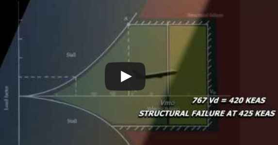
Why can't you source all of this? The Vmo/Vne were funny, as was the "structural failure" - and you have no idea how much irony is involved. Where did pilots for truth get "structural failure" at 425 KEAS.

A lie. Proved to be a lie by RADAR and Video. You got a source for your lie?
Your scale is bogus; pilot for truth Fake Vg diagrams start at over 90 knots, not zero knots. Fake Vg diagram - who made it? A failed photoshopped effort by pilots for truth.
inam56
(4 posts)from a frenchy with a bad english level
what balsamo does not show :
[IMG] [/IMG]
An interesting document from a test pilot about a complete load envelope :
http://www.mmopa.com/gallery/288_Sean%20Roberts%20-%20Flight%20Envelope.pdf
An other from the FAA who detail the FAA FAR 25.629 and the 1.15 VD zero flutter margin :
http://www.faa.gov/documentLibrary/media/Advisory_Circular/ac25-629omni.pdf
superbeachnut
(381 posts)... worse for Balsamo, the 757/767 were built to 1.2Vd standards.
inam56
(4 posts)Great !
Have you a source of this 1.2Vd standard ?
Everybody must also know, that this over-vd certification impose a sureness that flutter is not just near this marge.
FAA AC25-629
No significant mode, such as curves (2) or (4), should cross the g=O line below VD or the g=0.03 line below 1. 15 VD.
[img] [/img]
inam56
(4 posts)beachnut write: worse for Balsamo, the 757/767 were built to 1.2Vd standards.
Are you sur ? the FAA 767 A1NM certificate say 25.629 and not 23.629 ?
Built with 23.629 and certified with 25.629 ?
superbeachnut
(381 posts)Type certificate awarded 767 by FAA. July 30, 1982
When was 1.15 added after 1.2, for FAA 25.629
http://rgl.faa.gov/Regulatory_and_Guidance_Library/rgFAR.nsf/0/1AF764F921FAD01C862568E900643105?OpenDocument
http://rgl.faa.gov/Regulatory_and_Guidance_Library/rgFAR.nsf/0/9DD00A6A3FBA4A088525667200503326?OpenDocument
May 31, 2006, 25.629, yes A1NM ...
The 1.15 was 1.2, in the old days...
inam56
(4 posts)Thanks for the 1.2VD response.
An other question, is there a discussion somewhere in this forum about the Balsamo's Flight Simulator videos.